
Effective Technologies for Expanding Millimeter Wave Applications [Part 1] -- Beamforming, MIMO, etc.
This article provides a comprehensive overview of technologies that are considered effective in solving the millimeter wave dissemination issues introduced in "Challenges" for expanding millimeter wave use in 5G, as well as millimeter wave-related technologies that have been specified or are under consideration for specification in 3GPP and other standardization....
2023/12/05
Posted on 2023/12/05
In this article,Challenges" for expanding millimeter wave use in 5GOf the eight millimeter wave technologies, the first part of this report looks at three of them: beamforming, MIMO technology, and topology improvement technology. improvement technologies. (Click here for the second part.)
Challenges still lie ahead for the widespread use of millimeter waves. Several technologies are considered effective in resolving these issues. This paper presents an overview of technologies that are considered effective in solving these issues and millimeter wave-related technologies that have been specified or are being considered for specification in standardization by 3GPP and other organizations.
Fig. 4-1 summarizes the eight millimeter wave technologies presented in this chapter and the challenges each technology solves.
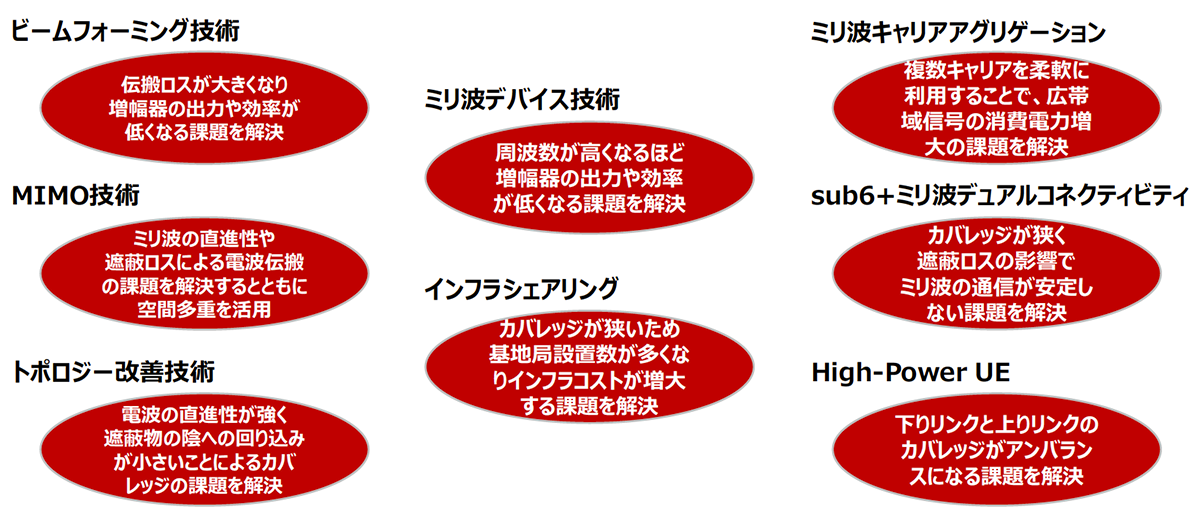
Fig. 4-1 Millimeter wave technology and challenges to be solved
Beamforming Technology
To solve the problem of high propagation loss and low amplifier output and efficiency, beamforming has become an essential technique for millimeter-wave As shown in Fig. 4-2, the use of a multi-element array antenna in the base station provides high array gain, which can solve the propagation loss problem [1 ]. In addition, by using the same number of amplifiers as or proportional to the number of antenna elements in the multi-element array antenna, the issues of low output and efficiency per amplifier can also be covered. On the other hand, increasing the number of antenna elements and increasing the array gain results in a narrower beam width, which requires directivity control with better tracking performance. The increase in array gain with multi-element array antennas is effective for expanding coverage not only on the downlink but also on the uplink.
Beamforming methods are classified into analog beamforming, digital beamforming, and hybrid beamforming, which is a combination of the three [1]. In addition to the use of multi-element antennas, analog beamforming is commonly used for millimeter wave due to its wide signal bandwidth. This is because high-speed DAC/ADCs supporting a wide bandwidth consume a lot of power, and analog beamforming is suitable because it requires the minimum number of DAC/ADCs (the same number as the number of signal multiplexes). The number of multiplexes for millimeter wave is generally two multiplexes with one antenna panel using VH polarization.
To cope with future traffic growth and increase the usefulness of millimeter wave, it is necessary to increase the number of millimeter wave multiplexes beyond two. There are methods to increase the number of multiplexes by analog beamforming using multiple antenna panels, but this increases the area of the array antenna as well as the number of circuits such as amplifiers, etc. One method is to divide one antenna panel and use multiple smaller antenna panels, but this method array gain is reduced. However, this method reduces the array gain. Therefore, by developing a millimeter-wave RF chip that supports multi-beam multiplexing and has the ability to amplify the multiplexed signals together with a single amplifier, it is possible to transmit multiple signals other than VH polarization from a single antenna panel without increasing the area of the array antenna and without reducing the array gain [2]. 2]. In the future, if low power consumption of high-speed DAC/ADC can be achieved, it will be possible to increase the number of multiplexes by applying digital beamforming or hybrid beamforming even at millimeter wave.
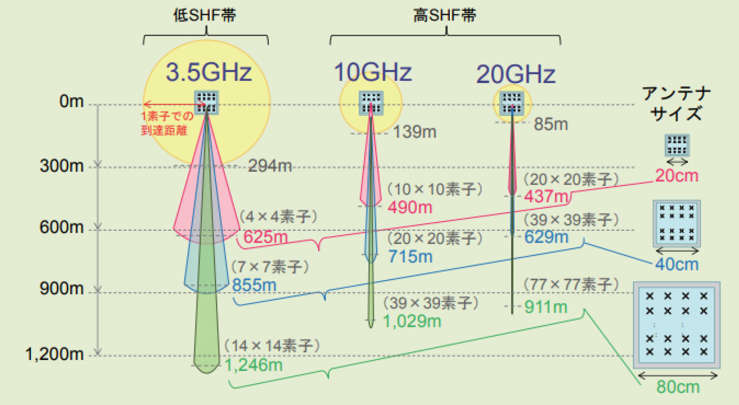
Fig. 4-2 Effect of beamforming
MIMO Technology
This section introduces future MIMO-related technologies that utilize spatial multiplexing as well as solve radio propagation issues such as millimeter wave linearity and shielding loss.
LoS-MIMO
Spatial multiplexing in MIMO is achieved by forming independent paths on the propagation channel through signal processing. In a multipath fading environment, the more multipaths there are, the higher the probability that the propagation channel will be one that can easily form independent paths. In the case of high-frequency bands such as millimeter wave, where radio waves have high linearity and are not easily reflected or diffracted, it is difficult to form independent paths because the correlation of propagation channels becomes high when the MIMO transmitting and receiving antennas are in the line-of-sight (LoS) environment. With in-sight MIMO (LoS-MIMO), the correlation of propagation channels can be lowered and multiple independent paths can be formed by properly arranging the MIMO antenna elements with respect to the transmission and reception distance.
In particular, when the element spacing is optimal, communication in MIMO eigenmode transmission is possible [3]. However, since the optimal element spacing is determined by the transmission/reception distance, its use has conventionally been considered for fixed communications. Recently, LoS-MIMO is expected to be used for mobile communications, and LoS-MIMO, which is robust to fluctuations in the transmission/reception distance, has been studied [4]. These LoS-MIMO techniques will facilitate the use of spatial multiplexing even in millimeter waves and improve the frequency utilization efficiency of millimeter waves.
Massive-MIMO/Distributed MIMO
Due to its high linearity, millimeter wave has a risk of communication breakdown if the radio wave is blocked by an obstacle. As a countermeasure, distributed-MIMO (Distributed-MIMO), in which many RAUs (Remote Antenna Units) are distributed as shown in Fig. 4-3 to ensure line-of-sight communications from RAUs to user terminals, is effective[5-7]. In particular, wide-area distributed MIMO, in which RAUs connected to a centralized base station are installed outdoors on utility poles, traffic signals, street lights, etc., and indoors on walls and ceilings, is expected to be introduced, in which multiple RAUs cooperate and communicate with each other [8]. Wide-area distributed MIMO allows user terminals to have redundant line-of-sight paths to multiple RAUs, thus improving the stability of millimeter wave communications.
Distributed MIMO is a technology that maximizes the degree of freedom of space by securing independent propagation paths in advance by arranging each antenna element of an array antenna at a greater distance than the carrier wavelength. Massive-MIMO (see note) includes two types of antenna element placement methods: collocated-MIMO, which is already in practical use in the sub6 band with elements placed as close as half a wavelength apart, and distributed-MIMO, in which antenna elements are placed at a distance from each other. In 3GPP, Rel-16/17, the following two types of MIMO were proposed: (1) collocated-MIMO, in which two base stations are located on each UE, and (2) distributed-MIMO, in which two base stations are located on each UE. In 3GPP, distributed MIMO using two transmission and reception points (Multi-TRP: Transmission and Reception Point) at the base station for one UE has been specified in Rel-16/17 [9].
(Note) Massive-MIMO
A technology that improves both spatial multiplexing and the quality stability of the radio propagation path by utilizing the degree of freedom of many independent transceivers. 5G has been developed and introduced with the aim of further improving frequency utilization efficiency through spatial multiplexing in addition to orthogonal frequency multiplexing and time division multiplexing in 4G.
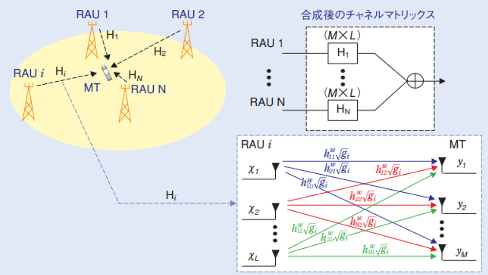
Fig. 4-3 Channel matrix from transmitter to receiver
Topology improvement technology
Millimeter wave has a strong directivity of radio waves and small wraparound effect into the shadows of obstacles, so it is a challenge to create an area outside the line-of-sight from the base station. Therefore, topology improvement technology is effective to improve reception quality in areas out of line-of-sight from base stations by installing relay stations and reflectors between base stations and terminals.
Relay stations are classified into two types: regenerative relay stations called IAB (Integrated Access and Backhaul) and non-regenerative relay stations such as repeaters. Repeaters are easy to install because they operate with only a power supply connection. They do not require GPS signals and can be used both outdoors and indoors, and they have the low latency characteristics required by 5G because they do not have digital signal processing, which causes high latency. Millimeter wave band repeaters are beamforming-compatible (with an integrated antenna), so that the donor side facing the base station and the service side facing the terminal are separated, and the units are connected with a single coaxial cable, enabling flexible area formation [10].
In addition, research on dynamic control of the radio environment, which was previously considered fixed, has recently progressed, as shown in Fig. 4-4, with studies including control of the position and orientation of relay stations by making them variable, and control of RIS (Reconfigurable Intelligent Surface) by reflecting incident waves in arbitrary directions using a metasurface reflector [10, 11]. Reconfigurable Intelligent Surface (RIS), which controls the position and orientation of the relay station by changing them, or by using a metasurface reflector to reflect the incident wave in any direction [10, 11]. Furthermore, technologies to bypass shielding by using dielectric waveguides, which enable low-loss transmission compared to coaxial cables, and area-enabling technologies that can flexibly respond to changes in the radio wave environment, such as changes in the layout of factories, by emitting radio waves from a part of the dielectric waveguide and freely changing or moving the position of radio wave emissions are being considered [12]. This technology can flexibly respond to changes in the radio wave environment, such as changes in the layout of a factory, etc. [12].
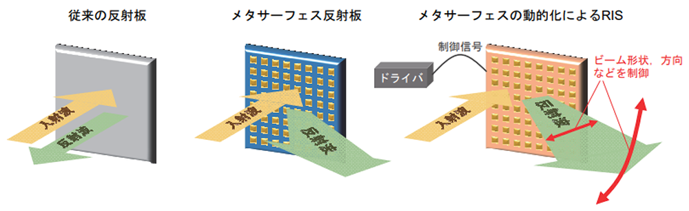
Fig. 4-4 Conceptual diagram of RIS using metasurface technology
References
- NTT DOCOMO Technical Journal, Vol. 23, No. 4, PP. 30-39, Jan. 2016.
https://www.docomo.ne.jp/binary/pdf/corporate/technology/rd/technical_journal/bn/vol23_4/vol23_4_005jp.pdf - Fujitsu, "RU Technologies," PP.4, 2023.
https://www.fujitsu.com/global/imagesgig5/RU-Technologies.pdf - K. Nishimori, et. al, "On the Transmission Method for Short-Range MIMO Communication," IEEE Trans. Vehicular Tech.
- M. Palaiologos, M. H. C. Garcia, R. A. Stirling-Gallacher and G. Caire, "Design of Robust LoS MIMO Systems with UCAs," 2021 IEEE 94th Vehicular Technology Conference (VTC2021-Fall), Norman, OK, USA, 2021, pp. 1-5.
- NTT DOCOMO Technical Journal, Vol. 15, No. 1, PP.55-59, Apr. 2007.
https://www.docomo.ne.jp/binary/pdf/corporate/technology/rd/technical_journal/bn/vol15_1/vol15_1_055jp.pdf - NEC, "Distributed MIMO in millimeter-wave frequency band to triple the number of simultaneous connections and transmission capacity under real office environment," , Jan. 2021.
https://jpn.nec.com/press/202101/20210125_01.html - KDDI R&D Laboratories, "World's First Successful Demonstration of Wireless Network Deployment Technology for Beyond 5G that Meets Individual Customer Needs," , Oct. 2021.
https://www.kddi-research.jp/newsrelease/2021/100701.html - NTT/DOCOMO/NEC, "World's First Successful Demonstration Experiment of Distributed MIMO in the 28-GHz Band to Keep Connected Without Worrying about Shielding," , Oct. 2022.
https://group.ntt/jp/newsrelease/2022/10/31/221031a.html - 3GPP TS 38.300, v17.3.0
- Denki Kogyo, "Repeater, Metamaterial Reflector (28 GHz band),"
https://denkikogyo.co.jp/elec/product/mobile/l5g/ - NTT DOCOMO Technical Journal, Vol. 29, No. 2, PP.15-39, July. 2021.
https://www.docomo.ne.jp/binary/pdf/corporate/technology/rd/technical_journal/bn/vol29_2/vol29_2_004jp.pdf - NTT DOCOMO Technical Journal, Vol. 29, No. 2, PP.7-12, July. 2021.
https://www.docomo.ne.jp/binary/pdf/corporate/technology/rd/technical_journal/bn/vol29_3/vol29_3_003jp.pdf
The content of this article has been excerpted and edited based on the 5GMF White Paper "Advanced 5G with Millimeter Wave Penetration, Version 1.0" published by 5GMF on March 31, 2023. The white paper was updated to Version 2.0 on July 3, 2011. To view the full document, please click5GMF Web siteDownload from